
Telecaster Wiring Diagrams
"the Blondie" 3-way Blade/Toggle with 1 Volume & 1 Tone

Switch Positions:
Position 1 - Bridge
Position 2 - Bridge/Neck (hum-cancelling)
Position 3 - Neck
This wiring schematic features a traditional 3-way blade OR toggle switch design. The middle position is hum-cancelling.
NOTE:
Polarity (Measured to the strings)
Neck = North
Bridge = South
"the Blondie" 4-way Blade for Series/Parallel Control
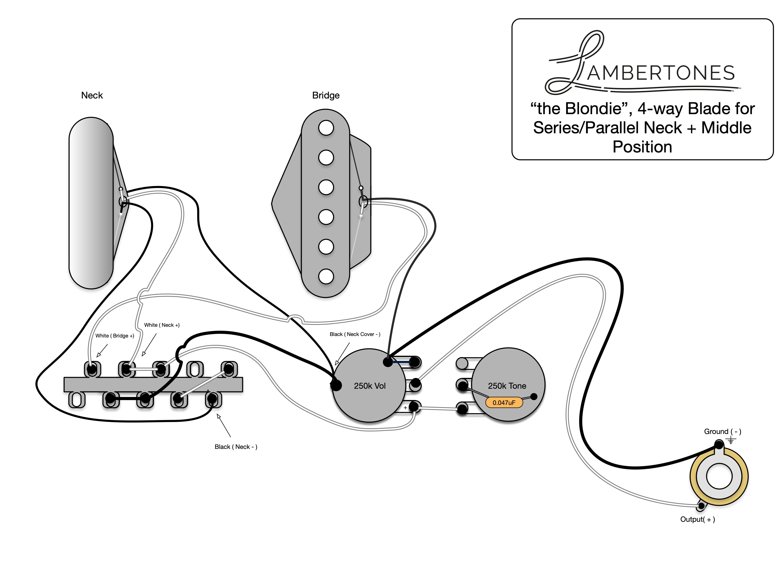
Switch Positions:
Position 1 - Bridge
Position 2 - Bridge/Neck (in Parallel and hum-cancelling)
Position 3 - Neck Position
Position 4 - Bridge/Neck (in Series)
This wiring schematic features a 4-way blade switch design adding the 4th position to include a series connection of the neck and bridge pickup. The tone from this option is considered "beefy". Imagine the cut and drive of a single coil with the thickness of a humbucker. Its not just a fancy addition, it's extremely usable and a highly recommended modification if you don't mind shifting away from a vintage style harness.
NOTE:
Polarity (Measured to the strings)
Neck = North
Bridge = South
"the Blondie" + "the Crema" 3-way Switch, 1 Vol, 1 Tone, 500k w/Resistor

Switch Positions:
Position 1 - Bridge seeing 250k (South polarity)
Position 2 - Bridge/Neck seeing 150k
Position 3 - Neck seeing 500k (South polarity to screw side)
This wiring schematic enables your single coil bridge pickup to see its desired potentiometer value of 250k while allowing your neck humbucker to see its desired pot value at 500k. The compromise is a darker middle position that, depending on the resistor used, will be approximately 150k resulting in a darker than normal middle position. This compromise is good for those that use their single coil bridge pickup.
NOTE:
Polarity (Measured to the strings)
Neck Screw Side = South
Neck Slug Side = North
Bridge = South
This diagram will work with 2-wire or 4-wire conductor. To utilize a push/pull pot for a coil-split middle position, purchase the 4-wire conductor humbucker and solder the red & white leads to "C1" on the CTS Push/Pull tone pot and solder a ground wire to the "1" position. This will improve the "dark" character of the middle position.
If you intentionally split the humbucker for the middle position you must split to the SLUG (North Polarity) side in order to maintain phase and hum-cancelling with the bridge pickup.
"the Ristretto" P90 Neck + "the Blondie" Tele Bridge
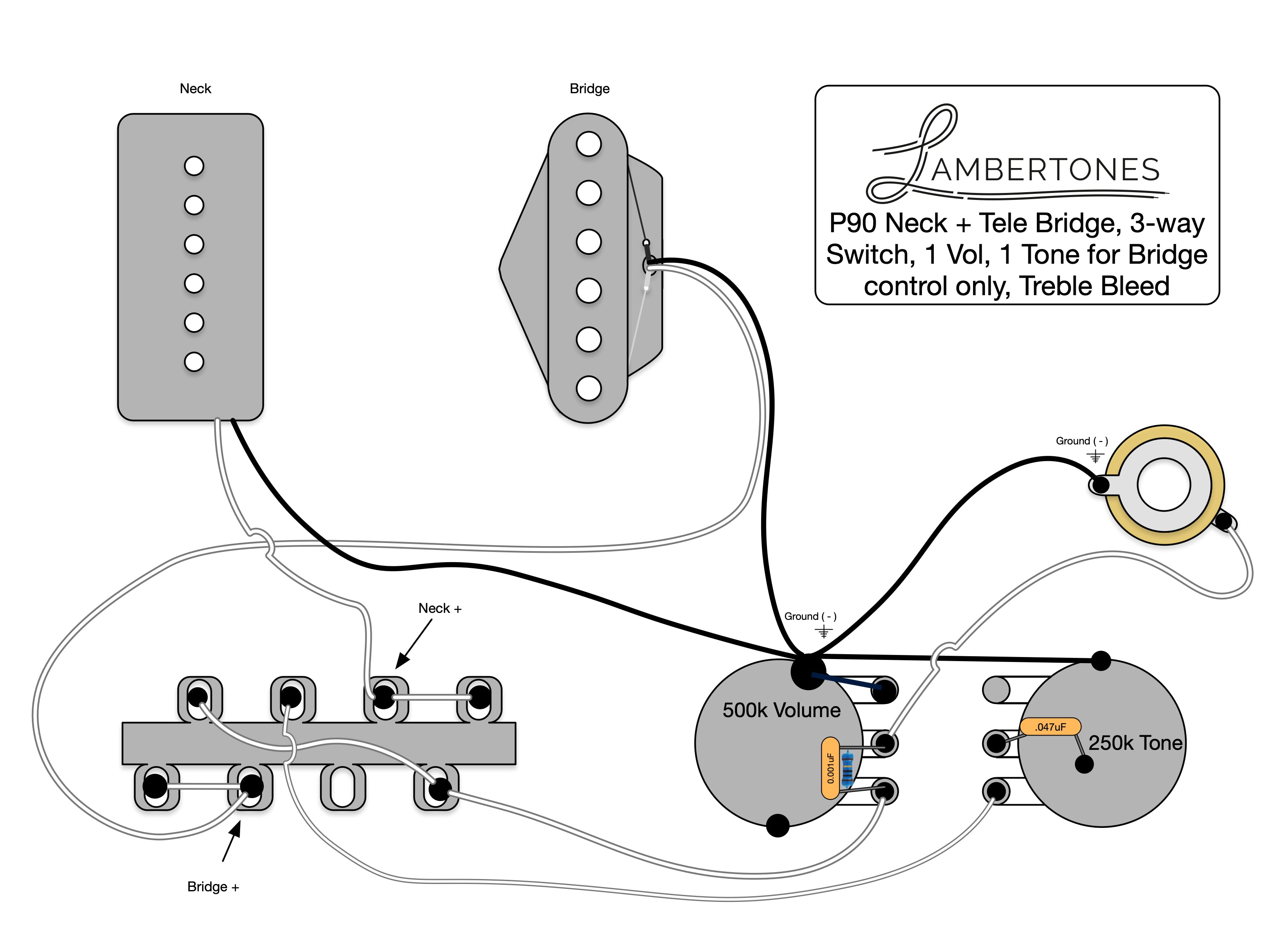
Switch Positions:
Position 1 - Bridge
Position 2 - Bridge/Neck (hum-cancelling)
Position 3 - Neck
This diagram allows the neck P90 to see its desired 500k resistance while giving the bridge single coil its desired 250k tone pot. The bridge ONLY will be affected by the tone pot. This wiring schematic features a traditional 3-way blade, a treble bleed circuit, and the middle position is hum-cancelling.
NOTE:
Polarity (Measured to the strings)
Neck = North
Bridge = South